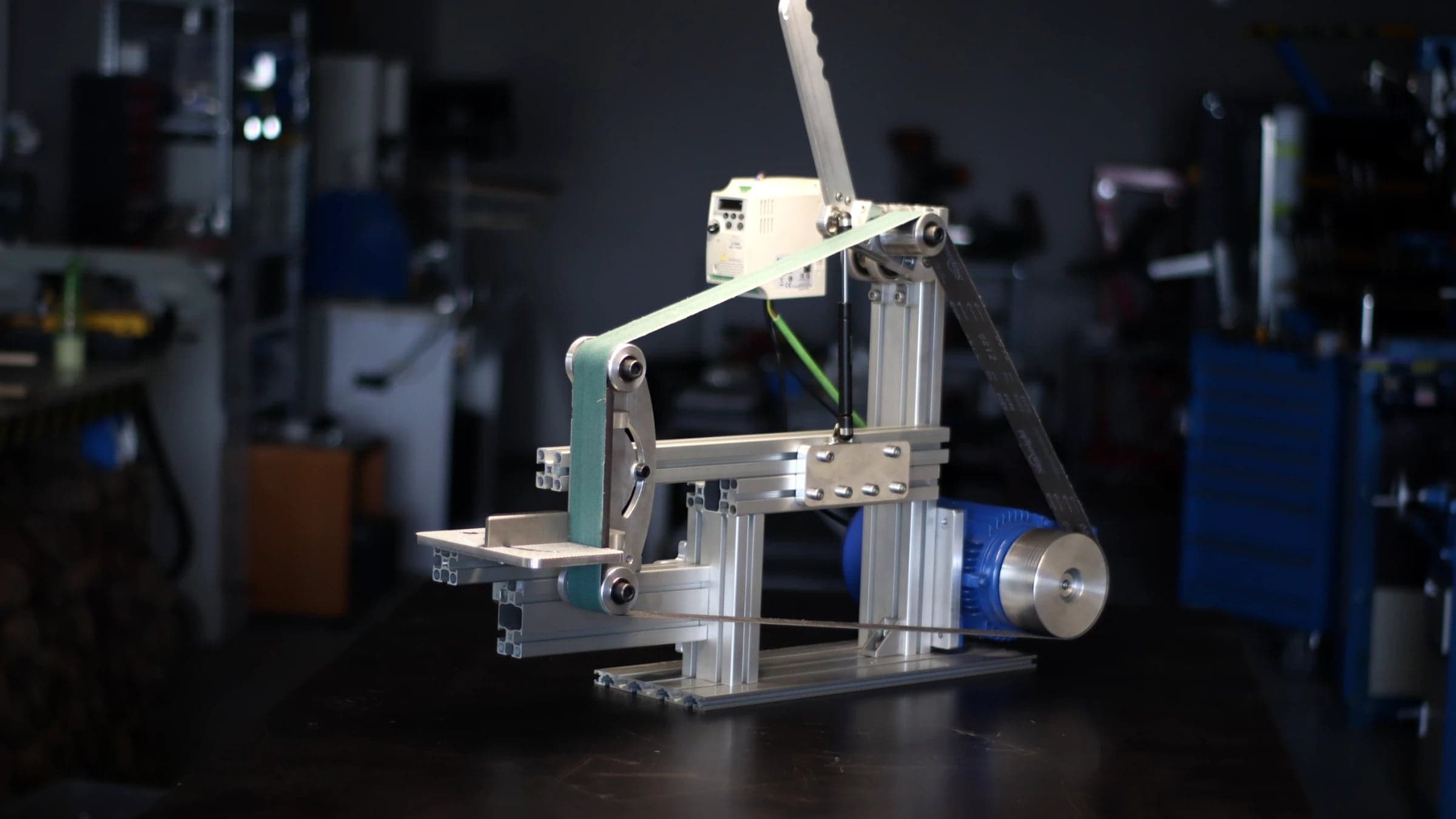
Belt Sander Tracking & Tensioning Mechanism
Personal project — design, machining & assembly
- Sector
- Personal R&D — Industrial equipment
- Year
- 2020
- Software
- Fusion 360
- Role
- Personal project — design, machining & assembly
Context
Full design and machining of the tensioning and self-centering mechanism for a DIY industrial belt sander — a personal R&D project built end-to-end in a home workshop in Spain, from Fusion 360 model to finished parts on manual lathe and mill. Today, client projects run through a network of professional manufacturers with industrial-grade machines and quality standards — this project stands as proof of the full manufacturing knowledge behind every design decision made for clients.
Problem
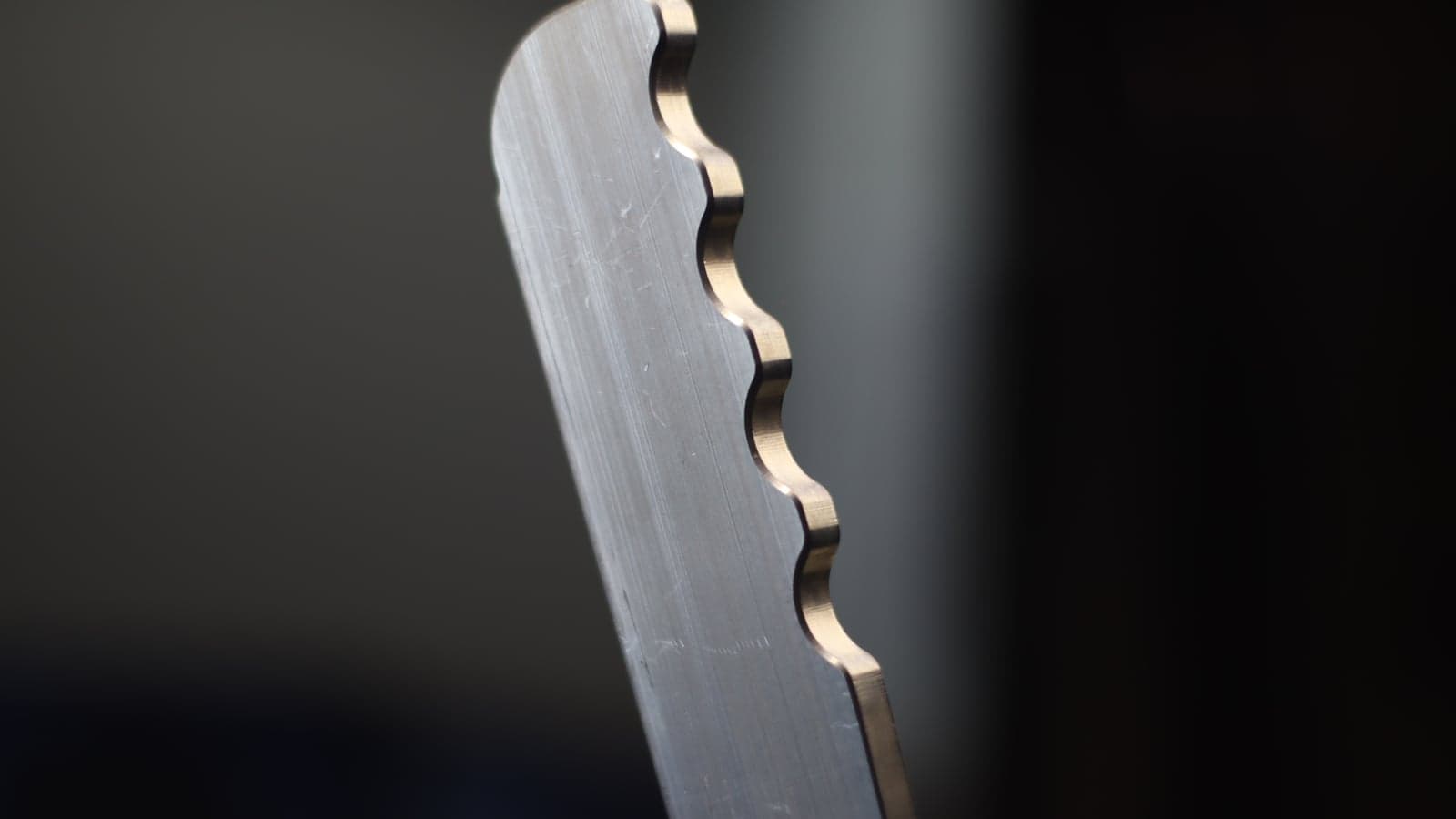
Belt sanders need the abrasive belt to stay centered on the rollers while running — a classic tracking problem. The mechanism had to tilt the roller shaft in a controlled way to self-center the belt, instead of relying on coarse manual adjustment. On top of that, the parts had to be machined with tight perpendicularity and individual fit on standard workshop equipment, with zero tolerance for play that would compromise tracking.
Process / Iterations
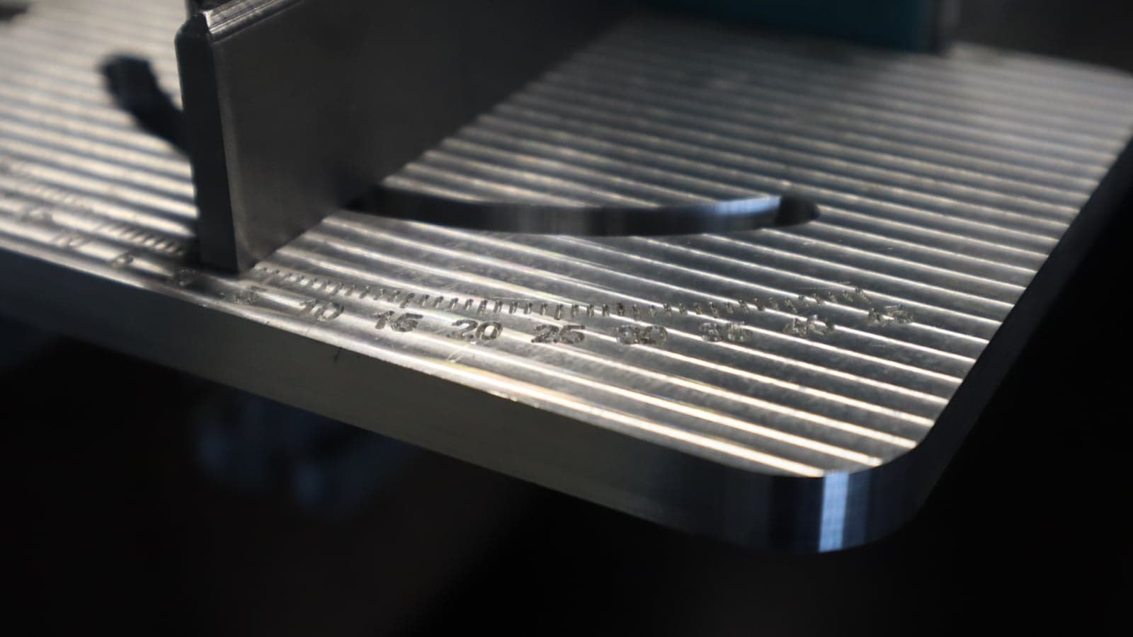
First iteration used 80×40 aluminum profile, dropped for lack of rigidity and non-standard pitch — redesigned around 45-series profile (90×45) for a consistent 45mm pitch and thicker wall throughout. The main roller shaft was turned to a custom fit against the bearings. Wheel spacers were faced on one side only, by design, to allow individual fitting once the CNC wheel program was finalized. A dedicated squaring jig was machined to guarantee the tensioning screw thread ran perfectly perpendicular — critical for the mechanism to self-center without drift — and a new automatic toolholder cut machining down to two operations per wheel. Two bushing-retention approaches were prototyped side by side; the block-and-cap version was selected over multiple grub screws for the production-intent design. Standard catalog hardware (Norelem positioning balls, M8 fasteners) was sourced where custom machining added no value.
Solution
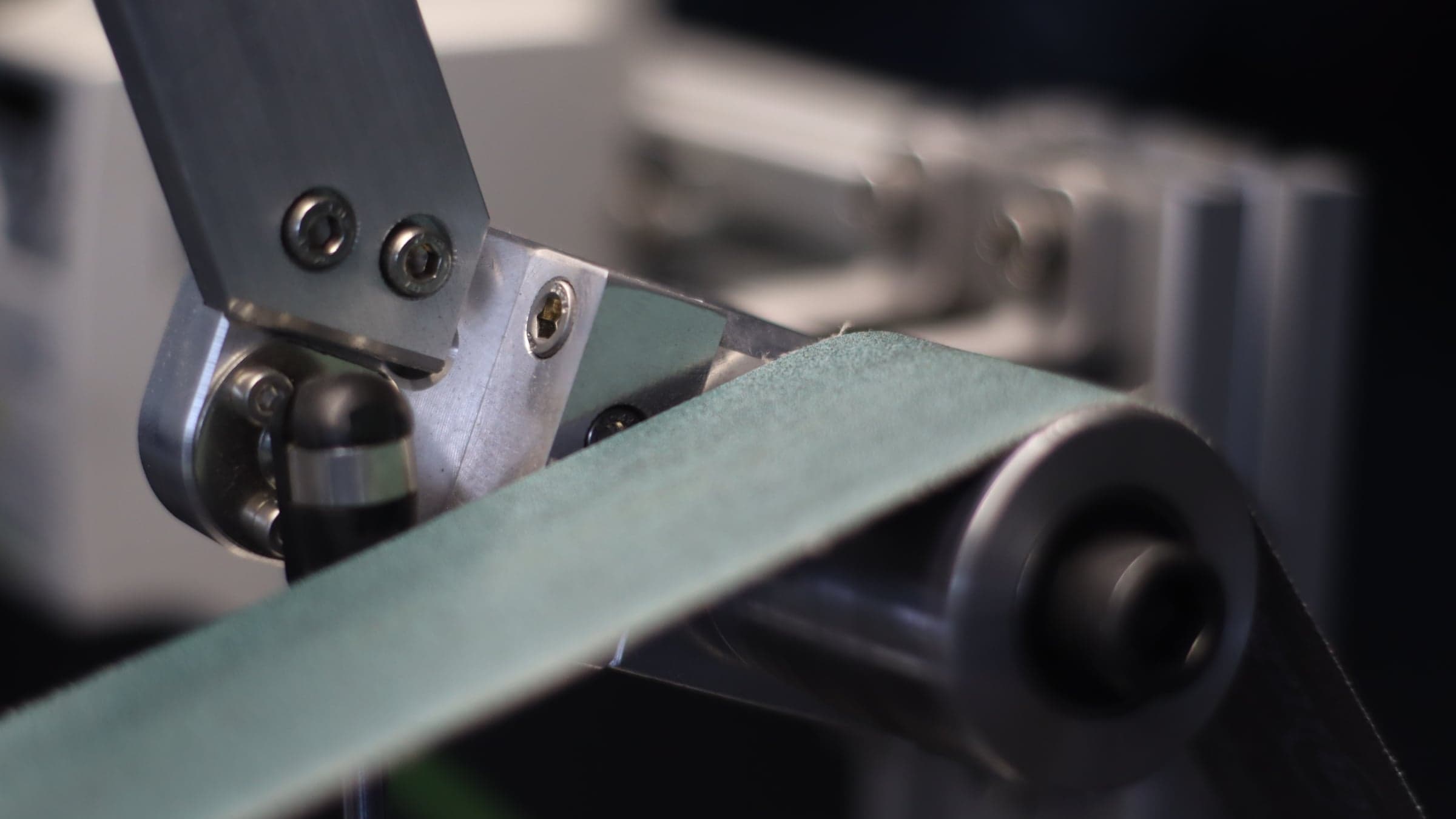
A pivoting plate mounted on a pivot screw, pushed by a gas strut and fine-adjusted with an M8 threaded screw against a flat bearing surface — that controlled push tilts the roller shaft just enough to self-center the belt. The full assembly stayed square without hours of dial-indicator setup, thanks to the purpose-built squaring jig used during machining.
Results
- Profile upgrade
- 80×40 → 45-series (90×45)
- Machining ops per wheel
- 2
- Gas strut force (prototype)
- 100 N / 10 kg
- Squaring method
- Custom jig, zero dial-indicator setup
Have a similar project?
Tell me what you need designed and I'll come back with an approach.
Send project brief